Ground-penetrating radar (GPR) is one of the most accurate non-destructive testing (NDT) methods available. To get the most from GPR surveying, it is absolutely essential to understand how GPR tools work and follow best practices when conducting surveys. The key areas to be aware of include: Target characteristics, survey design, correct antenna selection, best practices for setting up the system, practical tips to guarantee success in the field.
Know your target characteristics
Before taking a single step in the field, investigators must determine the characteristics of the target they are looking for and the surrounding material they are imaging through. Ground penetrating radar travels at different velocities, depending upon the material it is traveling through. For example, radar travels fastest through air, at about the speed of light – and slowest when traveling through water, about one-ninth the speed of light. Radar velocity for all other materials will vary somewhere between air and water.
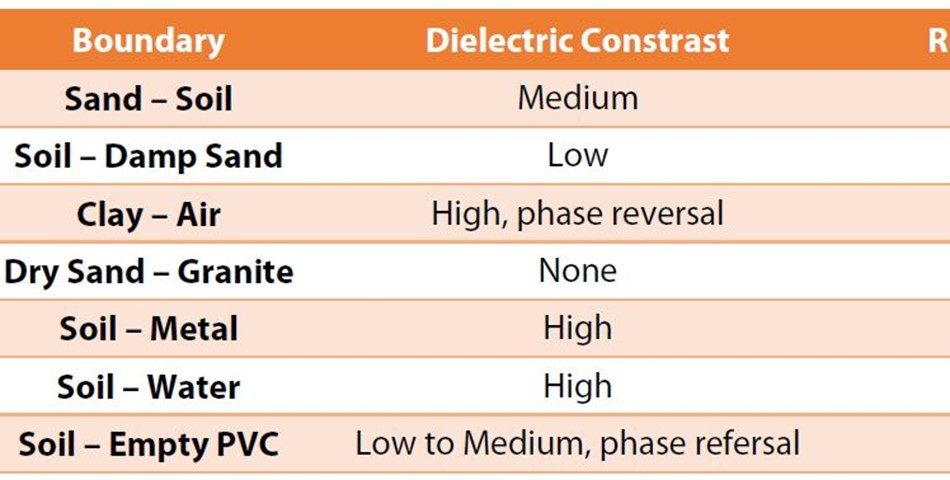
The value assigned to the GPR velocity through a material is called its dielectric. For example, air has a dielectric of 1 and water has a dielectric of 81, so all other materials have a value somewhere between 1 and 81. We use the dielectric value to calculate the radar velocity. GPR equipment is looking for differences in the dielectric of the material, so surveying may be more difficult when two materials have electrical properties that are too similar. Users must assess whether there is enough difference between the target they are looking for and the target’s host material. When scanning concrete, operators may be looking for electrical and telecom conduits. These can be tougher to locate than metallic reinforcing steel, due to the slight variation in dielectric from the concrete and these targets (especially if housed in PVC pipe).
A tip for overcoming this issue is turning the antenna 90 degrees from its normal orientation. Collecting data in this way may pick up different information, better allowing the operator to see plastic conduits, and give a better sense of concrete thickness. The same technique can work in utility locating and other layer mapping applications. In other words, if a GPR surveyor cannot see the pipe they think should be there, try turning the antenna 90 degrees. Or, scan in one direction, turn around, and come back in the other direction. Electrical conductivity of the surrounding material affects how deep surveyors can see. Since GPR emits electromagnetic energy, it is subject to attenuation (natural absorption) as it moves through a material.
If the energy is moving through a resistive (low conductivity) material such as very dry sand, ice, or dry concrete, the signal can penetrate a great deal of material. If a material is conductive (clay soil, wet concrete), GPR energy gets absorbed before it has had the chance to go very far into the material. GPR is best for inspecting materials with low electrical conductivity, like concrete, sand, wood, and asphalt. On the other hand, if the project involves locating a sewer line or an underground storage tank that is down 8-10 feet in wet, clay-filled soil, GPR might not be the appropriate tool for the job.
Choosing the best survey design
After determining the target’s electrical characteristics, as well as the size, type and orientation of utility lines, post tension cables, and objects of limited dimensions, including tanks and graves, investigators can design the survey. If very high confidence is necessary, the survey design should be based on a bi-directional grid, with spacing between the lines equal to the smallest dimension of the targets. Where this is not possible due to obstructions, time, or budget constraints, the survey design should include a large overview grid, which would be followed by one or more smaller focused grids.
If looking for cylindrical objects like an old oil tank or buried drums, investigators should choose a bi-directional grid; these targets may look flat when scanned in one direction, so they can be easily missed or mistaken for a soil layer. Using a bi-directional grid would identify a cylindrical target if the surveyor sees a flat layer in one direction and a hyperbola/arch in the other direction. For planar objects, including mapping the depth to bedrock, water table, or soil layers, the grid spacing would be determined mainly by the size of the area and allotted time, but one might also consider if there are any odd geologic features that need to be captured. These are typically larger features, and the undulating surface is a layer that can be seen by scanning in just one direction.
The survey design can use either two dimensional (2D) or three-dimensional (3D) scanning. With 2D scanning, individual profiles are collected and the data is often interpreted live on the screen. If the targets are utility lines or cables, and they are in a known direction, it may make sense to do 2D transects and mark them on the ground as they are seen in the data. 2D surveys are much quicker and easier, especially if surveying for one or two lines. They are also more effective if the survey is meant to locate geologic features, like bedrock or soil layers. Integration with GPS positioning is also quite common with 2D surveys. With 3D scans, operators place a grid on the ground and collect information on parallel and perpendicular lines.
Then, software in the field or office takes the individual profiles and models them together to get a top down, birds-eye view, analogous to an MRI picture of the ground. A bi-directional 3D survey is effective where the targets move in unknown directions. A 3D grid is also a better idea if one requires a high level of confidence in a target’s location, or where a good visual image is needed for a report. 3D surveys are also recommended if there are any potential dangers on the site that should be avoided. Another issue that affects survey design is the operator’s confidence in the target dimensions and how well the target boundaries are defined. If looking for the edges of a tank, or trying to locate where a water table transitions, set the survey boundary properly to capture what is required at the survey site. Target dimensions and confidence level controls the survey grid spacing used. For example, if the target is linear, like utility lines, and the surveyor knows what direction the features are running, the surveyor should cross linear targets perpendicular to their orientation, because they can be seen better. If this information is unknown, use a bidirectional grid. To obtain this information, consult as-built plans, and look for site features that provide clues. For example, there may be similar manholes on both sides of the site, showing that the pipe runs from point A to B. Or, there may be water valve covers at regular spacing along the road that allows one to determine the pipe orientation.
Selecting the correct antenna
Selecting the right antenna frequency for a GPR job depends on the size and depth of the target. A lower frequency antenna will provide deeper penetration, but the tradeoff is that the targets must be larger to be imaged. When looking only 1-2 feet beneath the surface, for example, when imaging in concrete and looking for very small reinforcing and conduits, use a higher frequency GPR antenna, which offers greater detail. For deeper targets, the primary and secondary choices are lower frequency antennas. These allow users to see deeper but one trades off the ability to resolve smaller features or targets. When scanning utilities, the mid-range antennas provide sufficient resolution to find 4-5 inch pipes. For going deeper, for example, mapping geological features 40-50 feet deep, low frequency antennas will work, because premium resolution is not required.
Best practices for system set up
Operators should take great care in setting up their system for optimal performance on each job. There are a varying number of available settings depending on the GPR equipment model. The factory setup recall can be a great starting point. However, users may have to make adjustments to ensure they meet two of the most crucial parameters: selecting the proper depth and collecting the ideal number of scans per unit. The proper number of scans varies depending upon the size of the target and the soil or material one is working in. A smaller scan spacing (more scans per unit) slows down the survey, so it is best to collect as many scans as possible while maintaining an acceptable survey speed. However, some projects may require devoting the extra time needed for very small scan spacing. More scans are required for smaller targets. For example, if the target is only 1 inch, take several scans per inch to guarantee getting a hit on the target. By contrast, if conducting geologic mapping looking for soil layers or the top of bedrock, one scan per foot or one scan per six inches would achieve the data density necessary to get the layer information required.
There is no such thing as too much site information
Apart from equipment and settings, proper GPR surveying relies on information about the site. Gather everything available. Collect site plans and as-built drawings. Talk to site maintenance staff and those who know local geology. Get any available nearby boring logs and geophysical information. Consult websites that contain databases of water wells that have been catalogued. These resources can assist with the expected location of buried targets, and the depth at which the wells hit water table or rock. This information will provide valuable data points to use when setting up the system and conducting a GPR survey. For geologic and cemetery mapping, consult records in the local library or other online resources. Pulling town records takes time, but it can be well worth it to ensure an accurate survey. Two great resources are the U.S. Department of Agriculture - Natural Resources Conservation Service’s Ground-Penetrating Radar Soil Suitability Maps, which are available for every state, and the Web Soil Survey, which provides online maps and data for more than 95 percent of the nation’s counties.
Tips and tricks to guarantee success
So, after carefully considering your target’s characteristics, designing a study to maximize the likelihood of locating the targets and features you are investigating, selecting the right antenna for the depth you are surveying, and setting the equipment properly, there are a few more tips to keep in mind: Equipment – Bring the proper equipment to the site, including paint, flags, stakes and cones. For making grids required for 3D scanning, make sure you have tape measures to create the grid. Don’t forget to bring a basic tool kit (tape, wrenches, and screwdrivers) to fix equipment on site. Visual site survey – When arriving at a site, begin by doing a general visual site survey. Draw a site sketch and take photographs, and look for service features like manholes and valve covers. Look for ports – For environmental surveys, look around the building perimeter for spill pipes, vent pipes, standpipes, or burial evidence. There is a port out there somewhere. Look for voids or depressions in the ground. Calibrate to known targets – Do some preliminary depth estimates on known targets. Pop a manhole cover, drain, or catch basin. Drill a test hole down to the top of a piece of rebar in concrete. Then measure down to get a point of reference. Scan right past that measured target and calibrate your equipment so the depth information for targets mapped on site is more accurate. Ensure proper power supply – Make sure batteries are charged. If you are going to be out in the field for 12 hours, bring sufficient batteries. Batteries for most GPR equipment last only 3-5 hours, so bring extras for all-day scanning. If working indoors, bring an AC adapter to plug into the wall.
Test in several areas – Make sure there is not a lot of change in signal or the soil or concrete does not drastically change across the site. Document everything! – Good notes are extremely crucial, even for projects that involve only painting or marking. Take notes on system settings and prepare a site sketch. No one will remember exactly what they did in the field without written notes. It is especially crucial to have good notes and site photos if someone is collecting data and handing it off for analysis. These notes and post-survey photos can also prove very useful if a project ends up in litigation. Take good care of your GPR equipment – Treat it like the sophisticated electronics that it is and you should get years and years of use out of it. From basic utility locating and marking, to concrete scanning for road and bridge repairs, to historical and archaeological investigations, GPR has an important role to play. But the usefulness of the data depends on careful consideration of target characteristics, proper survey design and antenna selection, and carefully setting up the system for optimal data retrieval.
By Brian Jones,
Senior Application Specialist/Sales
Geophysical Survey Systems, Inc. (GSSI)


